MC 302 GEOS – 5 MMI

5 AXIS CNC FLOOR TYPE VERTICAL SPINDLE MACHINING CENTER.
  • 5 axis (X, Y, Z, C, A) managed by CNC.
  • MMI = version provided with a device activated by a pneumatic/electronic combination dedicated to the automatic contemporary movement of the clamps.
  • Suitable for milling, drilling, tapping and cutting on the 5 sides of aluminum, PVC, steel and light alloys profiles; thanks to the 5 axis interpolation, the machine is able to execute composite cuts.
  • The X or longitudinal axis, the Y or transversal axis and the Z or vertical axis belong to the tool movement. They can be interpolated in linear and circular way on 3-dimension geometrical planes, belonging to X-Y-Z.
  • The C axis can be turned and positioned on all angles within 440° (± 220°); the A axis can be tilted and positioned on all angles within 250° (± 125°).
Geos

CARACTERÍSTICAS

Geos

FEATURES - MC 302 GEOS – 5 MMI

  • The axis slide on precision profile guides with ball recirculation and are driven by motors operated with digital systems.
  • The locking clamps slide on guide rail.
  • By using the disc cutter it is possible to carry out end-milling operations on both the ends of the work piece (end-milling cycle).
  • Milling operations can be performed with linear and circular interpolation of the axes X-Y-Z.
  • Available in 3 different longitudinal strokes: X = 8600 mm, X = 10600 mm, X = 12600 mm.
  • The hinging length stop are pneumatically managed.
  • The electric spindle is suitable for quick tool holder change.
  • The electrospindle is suitable for machining light materials, in particular aluminum, PVC and steel.
  • The rotating tool magazine with 18 positions is located on the carriage of the machine and thus reducing significantly the tool change time. It's available (optional) an extra tool magazine with a saw blade till Ø 450 mm also placed on the carriage.
  • The tool change can be carried out into any position belonging to the working area.
  • Up to 18 types of different tools can be physically seated.
  • The tools can be positioned manually by reference to a metric rod attached to the base. The availability of the position is indicated by the operating system process control.
  • As standard there are no. 8 clamps, can be managed with pneumatic control in groups of four.
  • The working area of the machine can be used as a single working field or be used in pendular mode obtaining 2 separate working zones, so reducing significantly the loading and unloading time.
  • Using a drill, a frontal drill or a tool for threading you can work on any face of the profile, oriented in the space.
  • The same applies to the use of a disc cutter (milling cycle) or a circular blade (cycle compound).
  • The tools cooling is realized through a centralised minimal system.
  • All slide ways and ball recirculation screws are lubricated through an automatic centralised system.
  • The base is designed to convey the machining scraps toward the centre.
  • Pre‐arranged for the inclusion of a motorized belt conveyor for evacuation of chips.

EQUIPO

EQUIPMENT - MC 302 GEOS – 5 MMI

  • No. 1 electric spindle liquid cooled, HSK F 63, rpm 24000, kW 10
  • No. 1 tools magazine at 18 places
  • No. 8 powered locking clamps
  • No. 1 Laser scanner
  • No. 1 Set of perimeter fence
  • Compressed air treatment unit (filter/reducer/lubricator)
  • PC desktop
  • Operative system Windows 7 ®
  • Display TFT 17″, keyboard QWERTY, mouse PS/2
  • CAD CAM 3D Graphic software
Geos

SOFTWARE

Geos

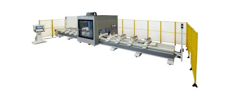
CAD CAM 3D - THE NEW MECAL 3D SOFTWARE FOR THE MANAGEMENT AND PROGRAMMING PROCESS OF MACHINES. - MC 302 GEOS – 5 MMI

Easy of use

  • Developed to render the approach for programming the machine tools to be the most intuitive possible, without the need to specifically know ISO language.
  •  It is characterized by a human machine interface, a machine purposely studied to render the usage of software and the development of all the necessary operations in the simplest possible way.
  •  All of the basic programming is already inserted as a macro, and can be applied to the various sides of the part even by means of the drag & drop function.

Advantages

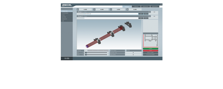
  • The representation of the work piece in 3D, how to lodge it inside the machine and of the tools to be used allows to avoid errors and reduce the chances of damaging the machine.
  • At the beginning of the process, a completion time will be provided; this facilitates the planning for production.
  • CAD CAM 3D is compatible with main calculation and construction software programs, like Wictop, Logikal, Klaes, Schücal, Opera, … (to mention the most well known).
  • It permits easy uploads of these programs, and programming of the machine with the aid of a barcode reader.

Simulator

  • With CAD CAM 3D it is also possible to purchase a simulator, that allows for verification of timing and production of work process without the need to actually test parts on the machine.

Automatization of production

  • The converter IGES imports external designs completed in SW CAD 3D and creates in automatic the program to process the work.
  • This characteristic is in high demand in the industry sector where the designs are often submitted in CAD like Inventor, Solid Works, Solid Edge, etc.
  •  With this software the work process of the machine limits the positioning of the clamped part and the selection of the work to be processed; this will be recognized by the automatic program.
  • In this phase, modifications pertaining to dimensions and type of work process can still be made, while some other selections can be excluded.
  • PAYLAŞ