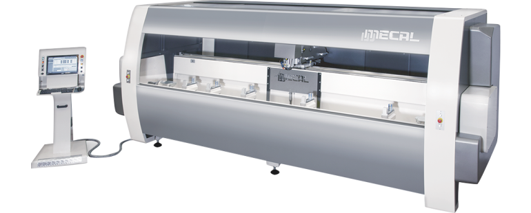
The workpieces are fixed with 5 pneumatic clamps, sliding on the tilting beam (4 axis). The beam can be positioned at any angle within ± 125°, managed directly by the numeric control.
The axis slide on precision linear guides and are driven by motors operated with digital systems.
The locking clamps slide on precision linear guides.
2 retractable reference stops (right and left) allow you to load profiles with complementary lengths, even with sections and different machinings.
The useful stroke for working bars is 4000 mm; for longer pieces, the differentiated machining cycle can be used, up to the double of the useful stroke (8000 mm).
The electric spindle is suitable for quick tool holder change.
The change of the tool holder is AUTOMATICALLY managed.
The tool magazine has 8 positions and is located in the middle of the basement. It can store angular units and a side milling cutter.
It’s equipped with a system with powered and independent positioning of the clamps able to move simultaneously. The independent powered system allows the positioning of each individual clamp unit in a very reduced time.
This system offers the possibility to work short pieces on the three faces of the profile with automatic repositioning.
The tools cooling is done through a centralized system that optimizes the required minimal lubrication.
Using a disk cutter, it is possible to work on both sides at the end of the profile (end milling cycle).
Milling operations can be performed with linear and circular interpolation of the axes X,Y,Z.
All systems handling axes are lubricated through an automatic centralized system.
Pre arranged to use a set of chips collector bins.
Pre arranged for the inclusion of a motorized belt conveyor with PVC belt for evacuation of chips.
VIDEO
Falcon
EQUIPMENT
EQUIPMENT - MC 307 FALCON TM MMI
STANDARD EQUIPMENT
No. 1 electric spindle air cooled, ISO30, rpm 18000, kW 5,5.
No. 1 tool magazine at 8 positions.
No. 5 clamps with independent powered system (MMI)
No. 2 hinging length stops, pneumatically managed
No. 1 Tool holders & Tools set
Compressed air treatment unit (filter/reducer/lubricator)
Automatic device for detecting the length of profile
Touch probe with multidirectional measuring mechanism (±X, ±Y, ‐Z)
Electricspindle ES 929 kW 7,5
Electricspindle ES 929 kW 7,5 with ENCODER (thread without axial compensation)
PVC belt conveyor for scraps
Drawers set for chips
Soundproofing panels coating the internal walls
CAD CAM 3D Simulator of machining
Interface drive for calculation program
CAD CAM 3D Drive interface for external CAD
Bar code reading device
Aggregate ISO30
Tool holders & Tools set
Falcon
SOFTWARE
Falcon
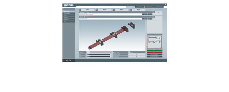
CAD CAM 3D - THE NEW MECAL 3D SOFTWARE FOR THE MANAGEMENT AND PROGRAMMING PROCESS OF MACHINES. - MC 307 FALCON TM MMI
EASY OF USE
Developed to render the approach for programming the machine tools to be the most intuitive possible, without the need to specifically know ISO language.
It is characterized by a human machine interface, a machine purposely studied to render the usage of software and the development of all the necessary operations in the simplest possible way.
All of the basic programming is already inserted as a macro, and can be applied to the various sides of the part even by means of the drag & drop function.
ADVANTAGES
The representation of the work piece in 3D, how to lodge it inside the machine and of the tools to be used allows to avoid errors and reduce the chances of damaging the machine.
At the beginning of the process, a completion time will be provided; this facilitates the planning for production.
CAD CAM 3D is compatible with main calculation and construction software programs, like Wictop, Logikal, Klaes, Schücal, Opera, … (to mention the most well known).
It permits easy uploads of these programs, and programming of the machine with the aid of a barcode reader.
SIMULATOR
With CAD CAM 3D it is also possible to purchase a simulator, that allows for verification of timing and production of work process without the need to actually test parts on the machine.
AUTOMATIZATION OF PRODUCTION
The converter IGES imports external designs completed in SW CAD 3D and creates in automatic the program to process the work.
This characteristic is in high demand in the industry sector where the designs are often submitted in CAD like Inventor, Solid Works, Solid Edge, etc.
With this software the work process of the machine limits the positioning of the clamped part and the selection of the work to be processed; this will be recognized by the automatic program.
In this phase, modifications pertaining to dimensions and type of work process can still be made, while some other selections can be excluded.